
Because of the large range of spindles and VDF's available it is not possible to make a one size fits all, this is how you do it video. All I can show is this is how I did mine and yours should be similar. Most of the real information is in the form of drawings and documentation on this page so read it carefully after watching this video.
If the reader finds something that they believe is wrong with the stup of the VFD please advise me and I will investigate and amend the documentation as necessary.
Warning
Please be careful when configuring the VFD. Incorrect settings can damage the VFD, Spindle or both.
Please use this documentation in conjunction with the video above.
Wiring the Spindle / VFD
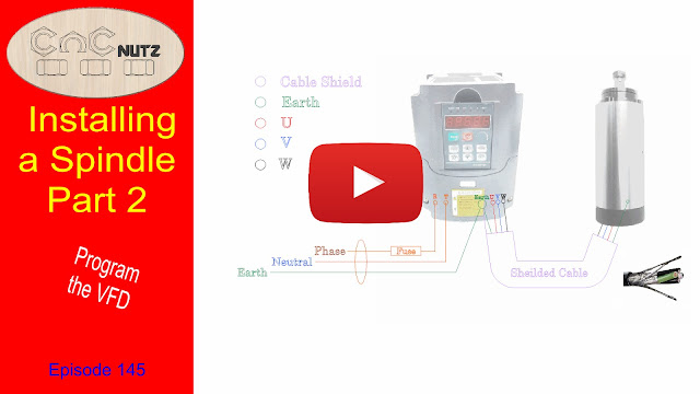
 The first drawing below shows how the VFD is wired to the mains and to the Spindle.
It is usual to use screened cable between the spindle and the VDF because of the large amount of interference that such equipment can generate. For those that live in the USA you can purchase screened cable from
Just look under Parts and Accessories > Wire


Wiring a Simple Remote Hand Control
The settings i have put into my VFD can be used for either a simple hand control or interfacing with a Gecko G540 stepper driver.
If you have an existing setup and wish to use the hand control the relevant registers to program are:
PD001, PD002, PD070 - PD076 inclusive
The values I have used should be ok for your setup with the exception of PD072 which you need to set to the frequency of your spindle.
See my Spindle VFD configuration document.

Spindle Configuration
To the best of my knowledge this info is correct
If the reader finds something that they believe is wrong with the setup of the VFD please advise me. I will investigate and amend the documentation as necessary.
This document shows how mine is configured so please use this in conjunction with the user manual for your VFD. Do not assume that the settings i have used on mine are correct as they are specific to the VFD / Spindle combination that I am using. Yours may be different.
Click on the links below to download the files.
VFD Configuration file
VFD Manual English Version This covers several models of Haug Yaug drives
Configure your spindle before connecting the Spindle for it's first run. I used a lower rated fuse in mine until I had it running properly and then installed a fuse of the correct rating. This was done incase the VFD was incorrectly configured it would blow the fuse rather than damage the spindle or VFD.
If there is sufficent interest in a hand control build I will make a video on building a proper spindle remote hand control. The one shown in the video was for demonstratuion purposes only to show what was possible with minimal effort. It is not intended for actual usage though if it was housed in a suitable box it would make an ideal control and would be much better than using the VFD front panel.
Great info, thanks!
ReplyDeleteThanks Richard
DeleteGlad it helps
Thanks. Hand control would be nice till I hook up a the usb
ReplyDeleteIt's nice and simple to make and in some ways I almost prefer it myself.
ReplyDeleteStill getting used to the auto start but I like the fact it turns off when the cut is done.
I suppose when you are used to doing something for so long it is hard to change.
Cheers
Peter
I am in process of getting and integrating the air-cooled 2.2kW spindle motor and inverter/control unit and I am curious if you, after having used the air-cooled unit for a while, wish that you had gotten the water-cooled version? Also, what size fuse did you put in the main line, both for testing and for final configuration?
ReplyDeleteI'm perfectly happy with the Air cooled spindle and don't regret it at all.
DeleteI used a 2 amp fuse for the initial setup and 10 amp for the final.
Normal running current with no load is 1 amp.
Cheers
Peter
Thank you sir... I really do enjoy your videos and learn a LOT. Keep up the good work.
ReplyDeleteWell, you have cleared up one thing Peter - air cooled is sufficient. Will your spindle accept 1/2 inch bits? Most spindles I have considered will only take up to 1/4. What is your opinion on using 1/2 inch bits? Are they a necessity for the hobbyist?
ReplyDeleteI found your videos and documents on spindles and VFDs extremely helpful. Thanks for everything you do.
ReplyDeleteThanks Carey, glad they help.
DeleteCheers
Peter
Sir My CNC SkM 1020 its spindle not working when i start any job using ncstudio then machine is going properly bit spindle is not spinning or turning to just machine is moving according to the job
ReplyDeleteIs there is a voltage problem or any other issue please help me
ReplyDeleteI am not familiar with your machine model or NC studio. You could have the VFD configured wrong, NC studio configured wrong or you breakout board wired wrong. You will need to test each individually to establish where your problem is and work from there.
ReplyDeleteHello, to see if you can help me configure the variables xsy-at1, the truth is that I can not do it and this happens to me. when I start to rise revolution
ReplyDeleteI'm desperate I do not know what to do
https://www.youtube.com/watch?v=Bp_MiCEkEvM
https://fotos.subefotos.com/86d0aa0172fdce8f2b8ce381ba60d48bo.jpg
https://subefotos.com/ver/?e40cbe140cef6367eed54d34fe3842a3o.jpg#codigos
Hello My friend, i have a Similar VFD model HUAJIANG YL620-A that looks a bit different but same concept, how to i Wirie "a Simple Remote Hand Control" to it as the inputs on my VFD are labeled a bit different?
ReplyDeleteMore Info:
18 GREEN INPUTS: Inputs: CM1 NO1 NC1 AO 13V 10V VI1 GND XVCC XGND X1 X2 X3 X4 REV FWD MO NC
8 SCRWE PLUGS INPUT: N L W/C V/B U/A FG +D -B
Info about some of the 18 green inputs: I think that NO1 and NC1 are apart of a relay inside the VFD.
Info about some of the 8 screw inputs: N and L are labeled as “The input”, the W/C V/B U/A are labeled as “Motor Output”, FG has a ground mark above it, +D -B are labeled as “Braking”.
I'm sorry but I am not familiar with your particular VFD so I am unable to help.
ReplyDeleteHopefully the people you purchased it off will be able to provide assistance.
Cheers
Peter
Peter,
ReplyDeleteHave finally given up with routers and have fitted and set up my spindle on my little Joe's CNC using the great information you so graciously share with other cncnutz
Just changed the noted areas to suit my spindle/VFD combo and had absolutely no issues with getting it to run correctly
Love what your doing, keep it up
Gully
Thanks Gully, Glad it helped.
DeleteCheers
Peter
HI Peter.
ReplyDeleteHave you ever come across this error message with your VFD (I have the same one) "E.Lun". The guys who made my CNC (Bionica Systems) reckon it has something to do with unstable supply, but running on sole supply has not corrected. I wonder if you have any thoughts? I have played with all sorts of solutions. Currently wondering if an overheating controller box (with consequent signal interference with DCM/FOR connector) could be an issue.
I have not seen that message at all. The manual asks you to check the input voltage is normal. Check whether there is a sudden change in load and check for a missing phase.
DeleteCheers
Peter
Hi Peter,
ReplyDeleteI have the same issue with my spindle, no grounding wire connected.
Would you mind sending a picture of the wire and where exactly you drilled the whole in the spindle body to connect it?
I am unsure where to do on mine, so I would appreciate if you could show us how you did yours.
Thanks and keep up with great work on your videos!
Cheers
Jackson
Hi Peter what do i do with the other end of the shielded earth to the spindle,,is it just left dormant in the top of the spindle
ReplyDeleteRegards Paul
Only one end of the shield is connected. The end at the spindle is left unconnected. A shield must never be connected at both ends. It will cause all sorts of weird problems.
DeleteCheers Peter
Excellent information Peter, Thank you, Kind regards, Michael Moore
ReplyDelete