Tuesday 25 April 2017

Installing a Spindle Part 2 - Episode 145

Today I am looking at wiring up the spindle and and programming the VDF (Variable Frequency Drive) to make the spindle run. I also built a very basic hand control for demo purposes to illustrate how remote control can be easily achieved without having to interface the VDF with your PC and yet still have reasonable control of the spindles speed turn it on / off remotly.

Because of the large range of spindles and VDF's available it is not possible to make a one size fits all, this is how you do it video. All I can show is this is how I did mine and yours should be similar. Most of the real information is in the form of drawings and documentation on this page so read it carefully after watching this video.

If the reader finds something that they believe is wrong with the stup of the VFD please advise me and I will investigate and amend the documentation as necessary.


https://youtu.be/hdFG3qxTTkM


Warning
Please be careful when configuring the VFD. Incorrect settings can damage the VFD, Spindle or both.
Please use this documentation in conjunction with the video above.

Wiring the Spindle / VFD

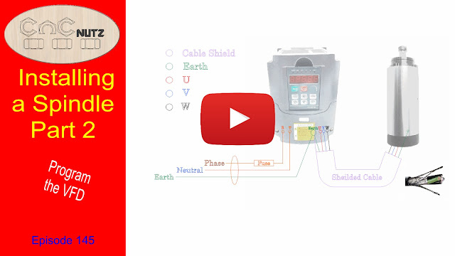
The first drawing below shows how the VFD is wired to the mains and to the Spindle.
It is usual to use screened cable between the spindle and the VDF because of the large amount of interference that such equipment can generate. For those that live in the USA you can purchase screened cable from   
Just look under Parts and Accessories > Wire


Click on me to download


Click on me to download

Wiring a Simple Remote Hand Control

The settings i have put into my VFD can be used for either a simple hand control or interfacing with a Gecko G540 stepper driver. 
If you have an existing setup and wish to use the hand control the relevant registers to program are:
PD001, PD002, PD070 - PD076 inclusive
The values I have used should be ok for your setup with the exception of PD072 which you need to set to the frequency of your spindle.
 See my Spindle VFD configuration document.
Click on me to Download a copy


Spindle Configuration
To the best of my knowledge this info is correct
If the reader finds something that they believe is wrong with the setup of the VFD please advise me. I will investigate and amend the documentation as necessary.
This document shows how mine is configured so please use this in conjunction with the user manual for your VFD. Do not assume that the settings i have used on mine are correct as they are specific to the VFD / Spindle combination that I am using. Yours may be different.

Click on the links below to download the files.

VFD Configuration file

VFD Manual English Version    This covers several models of Haug Yaug drives

Configure your spindle before connecting the Spindle for it's first run. I used a lower rated fuse in mine until I had it running properly and then installed a fuse of the correct rating. This was done incase the VFD was incorrectly configured it would blow the fuse rather than damage the spindle or VFD. 

If there is sufficent interest in a hand control build I will make a video on building a proper spindle remote hand control. The one shown in the video was for demonstratuion purposes only to show what was possible with minimal effort. It is not intended for actual usage though if it was housed in a suitable box it would make an ideal control and would be much better than using the VFD front panel.


Sunday 16 April 2017

New Spindle's first cut - Episode 144


This is the first run of the new spindle. New and improved with start, stop and speed under software control. Hadn't intended to go this far with the build but things got away on me and before I knew it I had built a new controller housing for the VFD and moved my Gecko drive and UC300ETH into it as well.

https://youtu.be/Yd-eptUKug0

Thoughts

The auto start is going to take a bit of getting used too.
Other than that it is looking good.


Friday 14 April 2017

Spindle Noise - Episode 143


Is a spindle quieter than a router?

Before taking the router off the machine it is a good opertunity to compare the noise against the new spindle. Doing it later would require reassembling the SuperPID so now is the best time to do it. The process is not scientific but only serves as a comparison between the two. 
The audio in this video used in the spindle / router comparison are recorded on the same microphone and it was not moved between tests. The levels are as recorded so offer a realisic comparison.
The test was conducted at 10,000rpm which was chosen because it is the speed I use to cut a lot of my projects. The SuperPID allows my router to run at slower speed but maintain the power. A spindle works the same way allowing it keep constant speed under load.

https://youtu.be/gyM8tHET-eM


The Results
 The router, as expected, was louder than the spindle but not by as much as I thought it would be. The 9db(A) difference represents an 8 fold increase in the power of the noise. The Decibel scale is logrithmic and a change of 3db(A) represents a doubling power. 3db(A) is also the smallest level increase that the human ear can distinguish. Exposure to noise levels of 85db(A) or higher can cause permanent hearing damage.

These tests are of only limited use as it is not normal to use a CNC machine and not cut anything. Once you start to machine your project the addition of dust collection and the sound of the router bit cutting through the material will easily increase the noise level above 85db(A) making the wearing of hearing protection manditory. Unfortunately I do not have level measurement of the old router while cutting to compare it against the spindle.
There will be an advantage when doing fine work as the cutter will not make a lot of noise. eg when I do a final pass on a 3d project I don't usually put my dust connection on and because of the minimal amount of material being removed the cutter makes very little noise.

I am looking forward to getting the machine up and cutting just to see how noisy it is.


Sunday 9 April 2017

Installing a Spindle Part 1 - Episode 142


I've been putting this job off for a wee while now.
I wasn't sure if the current Z axis on my machine would handle the extra weight of the new spindle or if it would be ok. The only real way of finding out was to install the spindle and see how it worked. Now that i have done the couple of projects i promised I would do I can now afford to have my machine down while i do this install. To avoid having to reinstall the old router if the spindle didn't work I have done the minimum until the spindle is tested and I am confident that it will work.
 In this video you will see the technique I use to test my Z axis to ensure it will work properly.

https://youtu.be/hcHw_sMqZ74


Additional loading

For those of you who think that 2.5kG / 5lb of additional load is overkill here are my are thoughts on it. The dust shoe weighs much less than the weight I used but in addition to the dust shoe weight you need to take into account the force required to crush down the bristles of the shoe. The sgoe bristles can support the weight I used without crushing. You cannot rely on the fact that the machine will be moving sideways when the dust shoe is being crushed as this will not be the case whern drilling holes. Gravity will help with this though. Over time tdust and dirt will build up and cause additional load on the Z axis and while it will take a lot of this to stall the axis I do not want my Z running on the edge but want a confortable safety margin built hence the large weight I used. Maybe it is overkill or maybe it isn't but I feel happier knowing the Z will work just fine no matter what I throw at it.